Steam noise
Noise Dampers of Steam and Gas Discharge into the Atmosphere
Efficient protection against negative impact of the high noise level during the steam discharge into the atmosphere
They are intended for reduction of the sound pressure level in the adjacent areas during the discharge of steam/gases into the atmosphere to the values required by the Customer and established in Regulation СН 2.2.4/2.1.8.562-96 and other regulatory documents.
General Description
Discharged medium: water steam, carbon dioxide, nitrogen, air.
The steam parameters in the pipeline in front of the discharge valve are as follows:
— pressure is not more than 27 Mpa,
— temperature is not higher than 570 C.
Installation place: on the discharge end of the discharge pipeline.
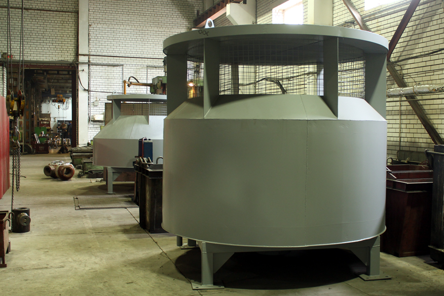
Body form: cylindrical.
Applied steel grades: Ст3, Steel 20, 09Г2С, 08Х13, 12Х1МФ, 12Х18Н10Т.
Sound-Damping Materials: thermoacoustic power boards ПТЭ-75 according to TR 5761-001-00126238-00, glass cloth ЭЗ-200 according to GOST 19907-2015.
According to the ratio of acoustic efficiency/weight, considering parameters of the discharged medium, the silencer are divided into:
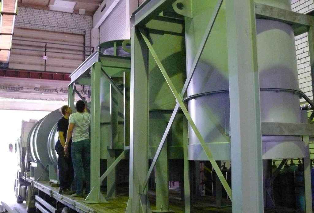
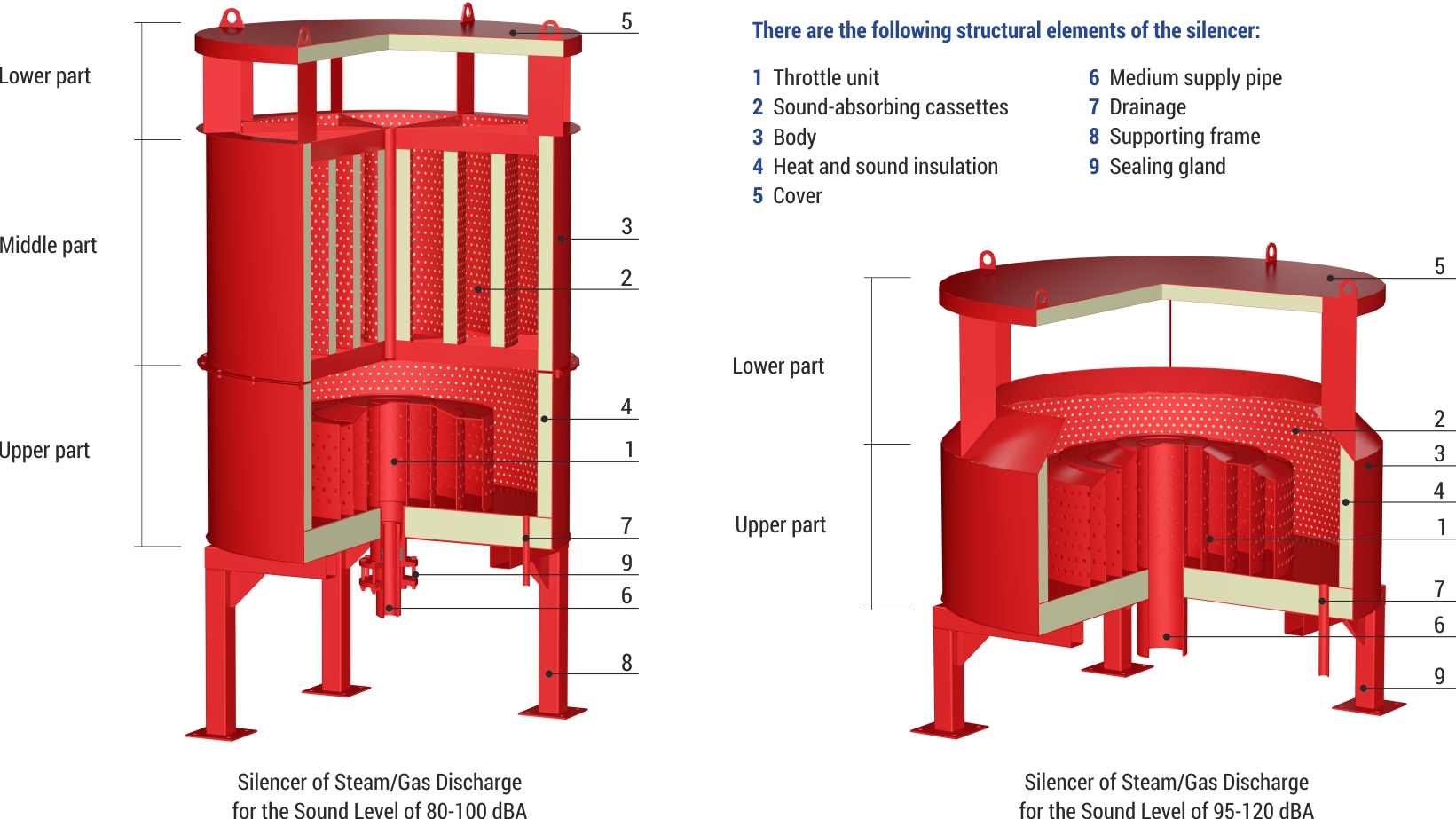
— dampers for the sound level of 80-100 dBA, fig. 109 (the larger weight and dimensions, with a cassette unit);
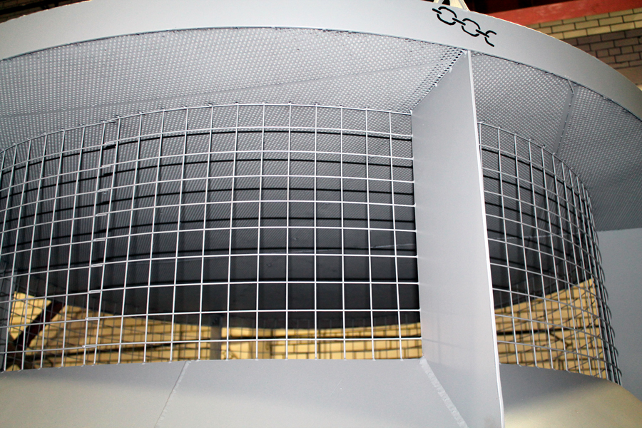
— dampers for the sound level of 95-120 dBA, fig. 110 (the lesser weight and dimensions, without a cassette unit).
A set of works in manufacture of a silencer includes:
— design according to the terms of reference of the customer;
— aerodynamic, acoustic and strength calculations;
— selection of materials;
— documentation development;
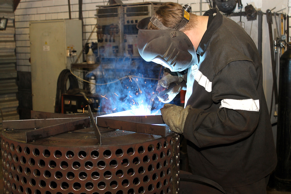
— noise damper production;
— delivery to the customer's warehouse.
 |
 |
 |
||
 |
 |
The operating principle of the silencer is as follows:
— The reduction of the sound pressure level when discharging steam into the atmosphere happens thanks to the effective braking and extension of the steam flow, speed reduction in the outlet section and flow separation into the smallest jets, as well as through acoustical absorption with sound absorbing boards.
— When the safety or discharge device is activated, the steam goes through the discharge pipeline below to the inlet fitting. Afterwards, it goes sequentially through the expansion chambers and throttle grids located on one axis. The steam is extended and reduces its speed. The throttle grids ensure alignment of the speed field and reduction of the maximum speed of the effluent flow to the required level.
— Then, the steam goes into the dissipative part of the silencer, where the sound is reduced in the sound absorbing boards.
The steam passes into the atmosphere between the cover and body, and the sound wave is additionally absorbed in the cover.
— The removal of moisture, produced as a result of the medium condensation passing through the silencer and settling down on its inner surfaces, is carried out to the drain pipe, located in the bottom of the lower part of the given device.
The noise damper structure is individually designed and calculated on the basis of the terms of reference (configuration data sheet).
The structure of the silencer is as follows:
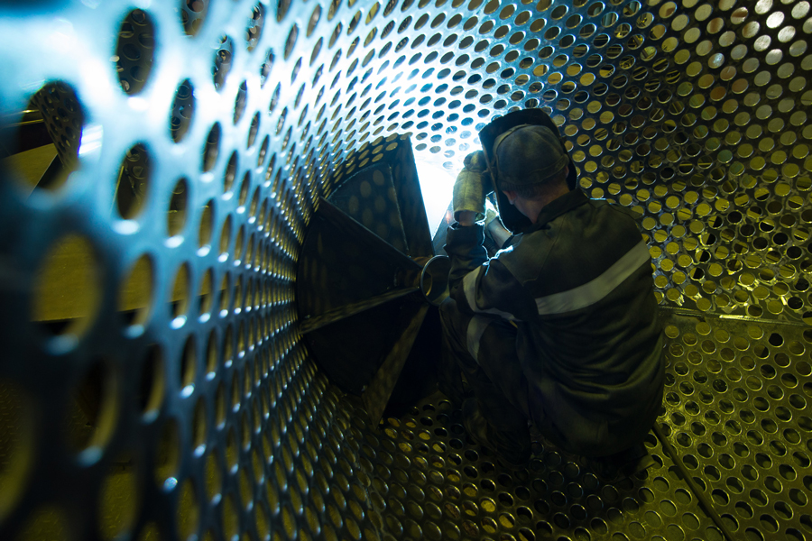
— The lower part contains a cylindrical body which is heat and sound insulated inside, cylindrical throttle grids dividing the inner body cavity into expansion chambers, a medium supply pipe and a drain branch pipe. The throttle grids below the perimeter are welded to the body bottom and closed with covers from above.
— The middle part represents a body continuation, inside of which sound-absorbing cassettes are installed. The cassettes consist of basalt boards ПТЭ, limited with glass cloth and perforated sheets from stainless steel 08Х13.
The sound insulation of the body is performed in the analogous manner.
The cassettes produce a sound-absorbing volume in form of ring channels through which the discharged medium is moving.
— The upper part represents a cover intended for prevention of atmospheric precipitations penetration into the silencer. It also contains a thermal insulation board board closed with glass cloth and perforated sheets.
— The steam supply is carried out through connection of an exhaust pipeline to the branch pipe of the silencer. The connection may be made as welded connection, flanged connection or with gland sealing for compensation of the thermal expansion of the discharge pipeline (at the customer's option).

 03:22
03:22

