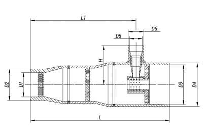
1101-50/100-ОП
BuyProduction according to TR 3113-003-15365247-2009
Connection: welded connection.
Structural versions: various designs depending on operating parameters of live
and reduced cooled steam. They differ from each other in dimensions, injection unit
version and structure of atomizing devices, as well as in the number of throttle grids.
Material of desuperheater bodies: steel of type 12Х1МФ, 15Х1М1Ф.
| D2, mm: | 76 |
| D1, mm: | 50 |
| H, mm: | 205 |
| L, mm: | 510 |
| DN, mm | Рр, MPa | T, ºC | Working Medium | L1, mm | D3, mm | D4, mm | D5, mm | D6, mm | Full Weight, kg | S1, cm2 | S2, cm2 | S3, cm2 | S4, cm2 | S5, cm2 | S6, cm2 |
| 50 | 9,4 | 540 | Пар | 360 | 112 | 133 | 22 | 29 | 23,9 | 5.5 | 9.4 | 0 | 0 | 0 | 0 |
The steam desuperheaters are intended for steam cooling-down and form an integral part of DS, PRDS and FRPRDS.
The steam is cooled-down in the desuperheater thanks to injection of cooling water or steam-water mixture.

The cooling water is injected with the help of atomizing devices (nozzles of mechanical and steam atomization, atomizing inserts or spraying jets), the flow through which is regulated with an injection valve. A signal for the flow control of cooling water is given at the temperature of the cooled steam in the pipeline behind the steam desuperheater. The steam desuperheaters may be equipped with one or several throttle grids which perform final steam reducing after the pressure reducing valve (for PRDS, FRPRDS).
The grids also serve as noise dampers simultaneously, while reducing the noise level during steam expansion in the desuperheater.
Installation: on horizontal and vertical pipeline sections behind the steam reducing valve.
The table demonstrates typical steam desuperheaters. However, the majority of steam desuperheaters is individually designed for specific operation conditions.

 08:54
08:54


