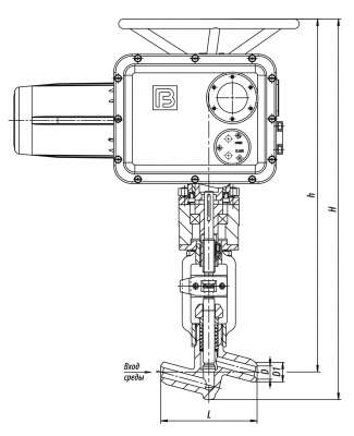
1с-11-3ЭМ Globe Valves
BuyProduction according to TR 2913-001-15365247-2004
Pipeline connection: welded connection.
Installation position on the pipeline: any position in the upper semi-sphere with regard to the neck. The valves (globe valves) are intended for outdoor installation and installation in closed premises.
Working medium supply direction: we recommend using of medium flow direction under the gate.
Gate sealability: according to class А GOST 9544-2015.
Climatic version: У, УХЛ, Т according to GOST 15150-69.
Placement category: 1, 2, 3 according to GOST 15150-69.
Manual override force (handwheel, lever): not more than 300 N.
The valves DN10 – DN65 may be manufactured with an easily replaceable seat from titanium or nickel alloy upon the customer's demand.
| H, mm: | 652 |
| h, mm: | 716 |
| L, mm: | 160 |
| D1, mm: | 32 |
| D, mm: | 22 |
| DN, mm | PN, MPa | Tmax of the Medium, ºC | Body Material, Steel | Working Medium | Operating Stroke, mm | TQ, N•m, maximum torque at spindle plug | ζ, not more than | Full Stroke Rotation Number | Control Method | Motor Model | N, kW | t хода, с. | Weight without Electric Actuator, kg | Full Weight, kg |
| 20 | 10 | 450 | 20 | Water-Steam | 20 | 80 | 5 | 5 | Э | Н-А2-08К | 0,25 | 10 | 10,1 | 30,1 |
| DN - Nominal Diameter PN - Nominal Pressure P - Pressure |
Tmax - Maximum Design Temperature Mкр - Spindle Torque t - Response time μ - Fluid Flow Coefficient |
h - Valve Stroke Kv - Throughput Capability F - Seat Area ζ - Resistance Coefficient |
The globe valves refer to the stop valves of two-position action.
They are only used for opening or blocking of pipelines by means of reciprocative movement of the shut-off device.
The globe valve control is carried out with the help of:
● a lever or handwheel (М);
● a built-in electric actuator (E);
● a universal ball joint (G);
● a cylindrical reduction gear unit (Cy);
● a cone reduction gear unit (Cn).
The valve configuration is adapted to application of electric
actuators manufactured by the following companies:
● Э – Barnaul Boiler Plant, LLC; CHZEM, Chekhov;
● ЭГ – GZ Elektroprivod, Moscow;
● ЭЧ – ABS ZEIM Automation, OJSC, Cheboksary;
● ЭН – BETRO-Tech, Berdsk;
● ЭМ – Tulaelektroprivod, Tula;
● ЭК – ZPA Ресky, Czechia;
● ЭД – АUMA, Germany;
● other manufacturers with standard connection units.
The allowed values of operating pressures and temperatures for the fittings may differ from those ones given in the table with technical specifications and are chosen in accordance with GOST 356-80, provided that they shall not exceed the limits prescribed by the respective State Supervision Rules and Standards for these materials and operation conditions.
According to GOST 356-80, the items designed for the ultimate pressure allow their application on operating parameters within the following range:
● at PN 10 MPa – from 10 MPa, 200 ºС to 3,6 MPa, 455 ºС;
● at PN 25 MPa – from 25 MPa, 200 ºС to 9 MPa, 455 ºС;
● at PN 6,3 MPa – from 6,3 MPa, 200 ºС to 2,3 MPa, 455 ºС.

 06:25
06:25


